![]()
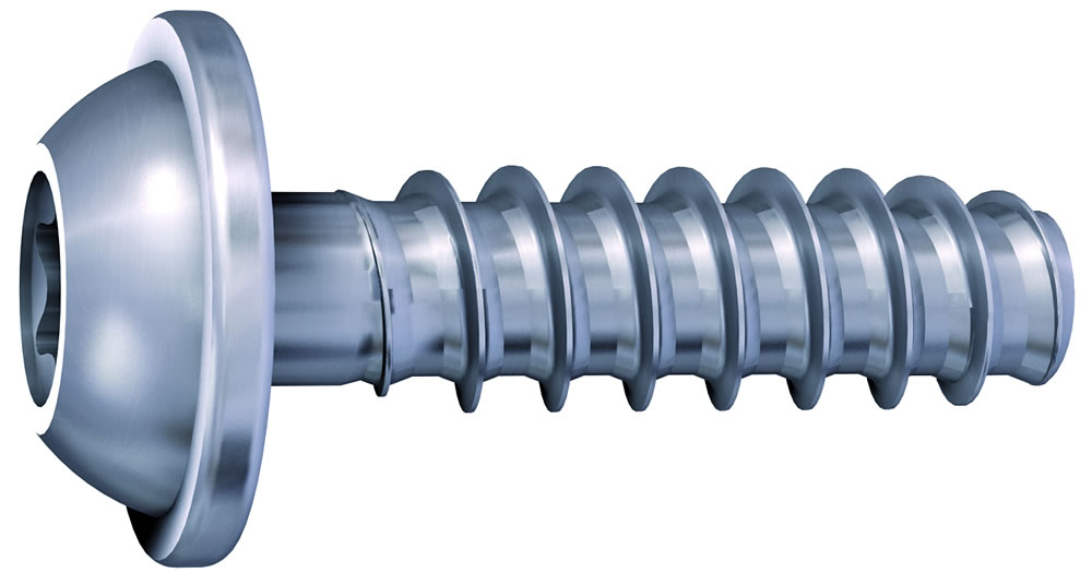
New Thin Thread Technology for Thermoplastics
Reduces radial stresses
Eliminates the need for inserts
Allows for thinner and shorter boss designs
Provides higher torsional and tensile strengths compared to the original PT® Screw
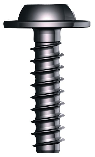
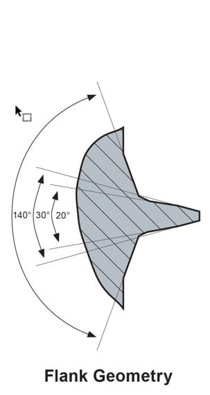
Multi-compound 30° flank angle and root for dynamic safety
Increased vibrational safety by improved pitch
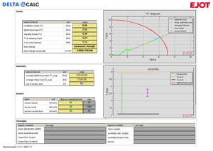
Delta Calc Software validates applications, speeding up engineering development time
A new flank geometry was designed for optimal flow of the plastic material during the fastening process.
The service life of the joint is substantially increased under static and dynamic stress.
Up to 50% improved torsional and tensile strength (for the same nominal diameter).
Using shorter fasteners and smaller diameters is possible due to a larger core and reduced thread pitch length.
The DELTA CALC calculation program was created to provide theoretical performance data in many common materials used today.
It increased vibrational safety by improving pitch.
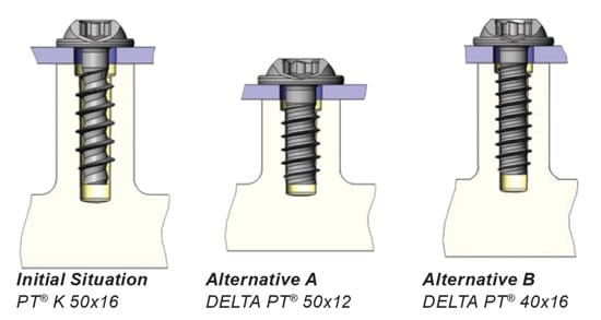
The graphics on the left display the possibility of reducing fastener size by switching from a PT® fastener to a Delta PT® fastener. Alternative A represents a reduction in length, and Alternative B represents a reduction in diameter. In each scenario, total thread flank engagement is maintained due to the reduced pitch of the Delta PT®. Because of this, boss diameters or heights can be reduced, resulting in material savings without sacrificing joint performance.
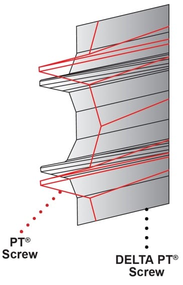
An extended core diameter and an optimum thread design improved the permanent strength of the fastener cross-section.
To further increase dynamic safety, the thread teeth were stabilized, leading to improved safety against flank breakage. The improved pitch allows better flank engagement and provides better conditions against stress fracture of the thread flank.
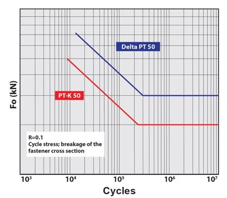
Cycle stress by PT® and Delta PT®;
breakage of the fastener cross-section
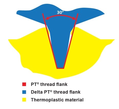
The newly developed flank design forms the optimum thread without any material damage.
Utilizing a detailed analysis of the material disposition while thread-forming, it was possible to create an optimal flank geometry. During material deformation, the lowest resistance can be observed, which prevents friction-inflicted heating.
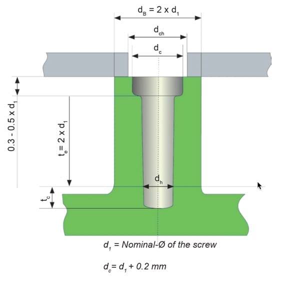
In principle, the boss design should correspond to the following design recommendation. The counterbore is particularly important, as it ensures favorable stress, thus preventing boss cracking. In addition, the counterbore acts as a guide during setting and initial thread forming.
The most favorable hole diameter is:
dh = 0.8 x d1
The hole diameter may be increased for higher-filled materials or materials with increased strength.
Design recommendations have been developed through laboratory tests. In practical operations, variations of these recommendations may occur due to:
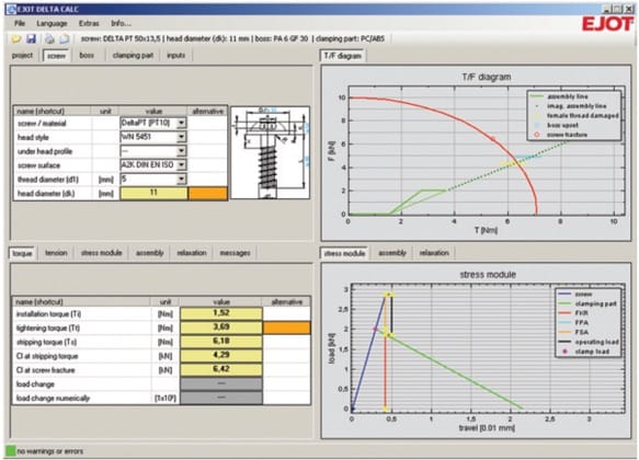
This calculation program was developed specifically for the Delta PT® product.
The software can validate application designs by providing theoretical assembly parameters and performance, dramatically speeding up engineering development time.
![]()
The Evolution of Direct Fastening into Plastic
EJOT DELTA PT® DS
New Technology for Thermosets and Composites
EJOT DELTA PT® S
Technology for Thermosets and Composites