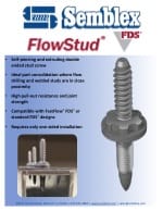
Flow Drilling Screw Technology
Benefits
Installation into aluminum or steel sheets without the need for pre-punched or drilled holes
Hole alignment issues minimized
Chipless thread forming
High safety window between installation and stripping torque
High shear and pull-out resistance
Dynamic in high vibration applications
Compatible with metric machine screws for service
Features
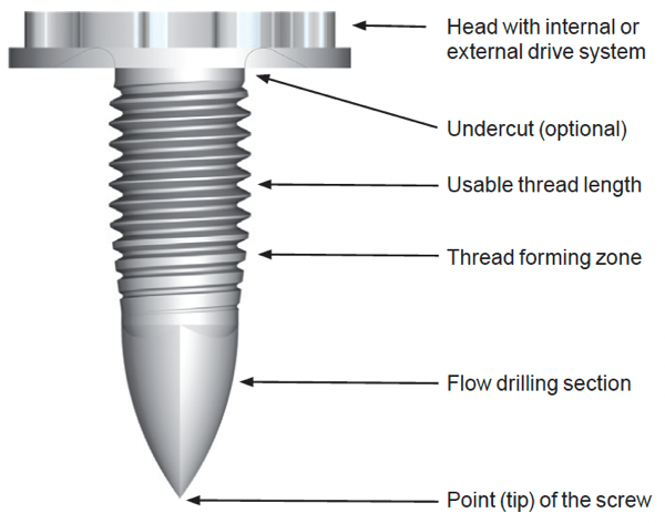
Multiple point designs available depending on application requirements
Head undercut present to capture upward material flow
Unique head-drive combinations for maximum assembly efficiency and fastener weight control

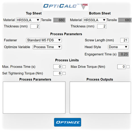
OptiCalc Software validates applications, speeding up engineering development time
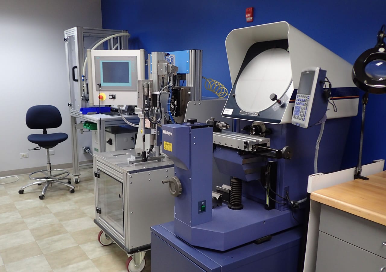
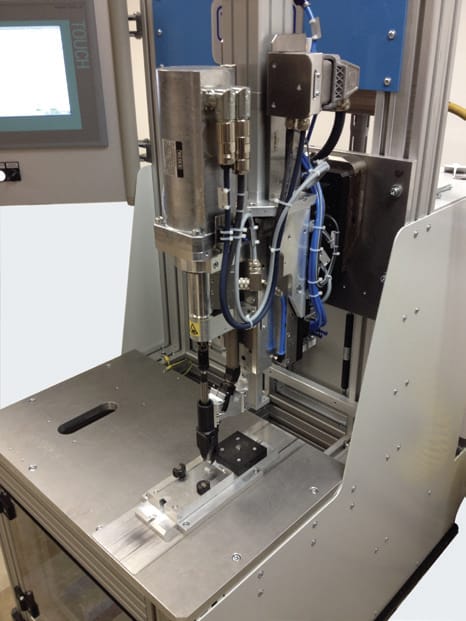
FDS Application Testing Equipment
Today’s designers continue to search for ways to maximize product performance and efficiency. One approach that is being taken in the automotive industry and elsewhere is lightweighting. The utilization of thinner and lighter materials like aluminum can bring about significant weight reduction. The joining of these materials is critical to meet or exceed current performance levels. There have been many advancements in fastening technologies for these thin sheet joints. However, the majority of products require two-sided access for installation. The Semblex FDS® flow drill screw was developed as an innovative single-sided fastening solution for these lightweight, thin sheet joints.
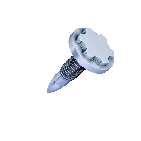
FDS® Features
FDS® Benefits
- One-sided access is required for the assembly
- Pre-drilling or punching of joined material is not required
- Chip-less forming of female threads
- Deep extrusion was created, resulting in high thread engagement and joint strength
- Excellent drive-to-strip differentials for increased safety margins
- Eliminates welding costs and workplace environmental concerns
- Standard metric thread screws can be used in repair situations
- Effectively used with adhesives for an enhanced joint performance
Assembly Process
FDS® Assembly without Clearance Holes
- No part preparation required like pre-drilling or punching
- Undercut design required to capture up-flowing material
- Down-holder (pressure foot) required to resist movement of the top layer
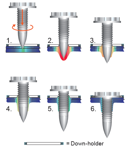
- Warming up the sheet metal by axial end load and high-speed
- Penetration into the material
- Forming of the extrusion
- Chip-less forming of a female machine thread
- Installation
- Tightening with the pre-set torque
FDS® Assembly with Clearance Holes
- Beneficial when top layer material is incompatible with the flow drilling process
- Simplified head design may be used
- Down-holder (pressure foot) not required
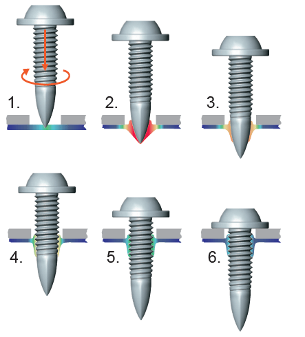
- Warming up the sheet metal by axial end load and high-speed
- Penetration into the material
- Forming of the extrusion
- Chip-less forming of a female machine thread
- Installation
- Tightening with the pre-set torque
Assembly Equipment
Fastening Equipment Selection
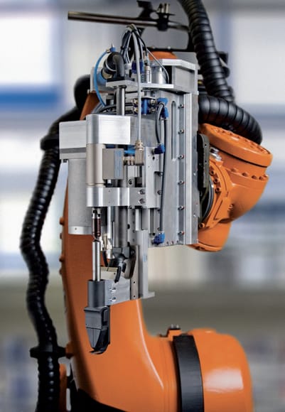
FDS® assembly requires high-speed automated drive systems that control and adjust speed, torque, axial load, and depth throughout the multi-stage installation process.
Programmed assembly parameters are dependent on the following joint characteristics:
- Sheet thicknesses
- Number of layers
- Material properties
- Surface treatment
- Overall joint requirements
FDS® installation equipment is commonly paired with robotics to allow for pre-programmed locating and assembling of joints in various spaces and positions.
Semblex has relationships with several installation equipment manufacturers and integrators that can assist you with selecting, building, and installing equipment.
Test Equipment
Semblex can perform drive testing utilizing a test stand-mounted drive system.
Validation testing can be performed on material coupons to validate the feasibility of different material stacks and to help develop appropriate program parameters.
Tensile test equipment can also gather peel-and-shear performance data.
Please contact Semblex Engineering Services to discuss any testing needs you may have.
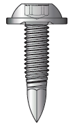
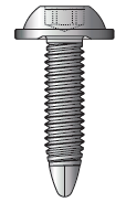
FDS® Designs
Standard |
PKS |
|||||||||||||||
|---|---|---|---|---|---|---|---|---|---|---|---|---|---|---|---|---|
 |
 |
|||||||||||||||
|
Material and Heat Treatment |
Case-hardened mild steel |
Case-hardened mild steel |
||||||||||||||
|
Finishes |
Zinc with passivation Additional lubrication is avoided in most applications to ensure the adhesion of cataphoretic coating. |
|||||||||||||||
|
Application |
No pre-hole in select layers |
Pre-hole in all layers |
||||||||||||||
|
Installation |
|
|
||||||||||||||
|
Characteristics |
Preferable for automated assembly Tolerance-free assembly because of no misalignment with clearance holes. Extremely high joint strength Ideal screw for safe assembly and dynamic loads |
Preferable for manual assembly Due to a bigger clearance hole compared to the smaller pilot hole, some tolerances can be compensated Low-end load required |
||||||||||||||
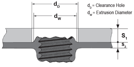
Design Guidance
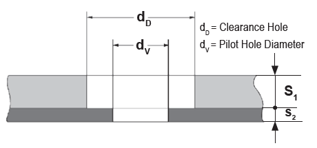
Recommended clearance hole diameter (dD)
Flow drilling with the FDS® screw creates an extrusion in both the fastening and driving directions. This material can be contained when using a clearance hole, avoiding the need for undercut head designs. The following are recommended clearance hole sizes.
|
FDS® Size |
M4 |
M5 |
M6 |
|---|---|---|---|
|
dD |
5.1 - 5.7 |
6.7 - 7.4 |
8.2 - 9.1 |
Recommended pilot hole diameter (dV) for Type PKS
The optimum hole diameter depends on the respective range of requirements on the joint and should be specified according to the application.
|
FDS® Size |
M4 |
M5 |
M6 |
|
|---|---|---|---|---|
|
sheet thickness S2 [mm] |
0.5 |
1.5 - 2.0 |
1.8 - 2.5 |
- |
|
0.63 |
1.6 - 2.2 |
1.8 - 2.5 |
2.0 - 3.0 |
|
|
.75 |
1.8 - 2.5 |
2.0 - 2.8 |
2.2 - 3.2 |
|
|
.88 |
2.0 - 2.6 |
2.2 - 3.0 |
2.5 - 3.5 |
|
|
1 |
2.2 - 2.8 |
2.6 - 3.4 |
2.8 - 3.8 |
|
|
1.25 |
2.4 - 3.0 |
3.0 - 3.8 |
3.4 - 4.5 |
|
|
1.5 |
- |
3.4 - 4.2 |
3.8 - 5.0 |
|
|
>1.50 |
- |
4.2 - 4.6 |
5.2 - 5.6 |
|
Part Length Considerations
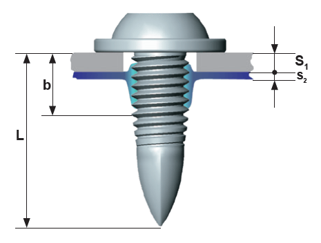
Standard FDS® Design
b = S1 + 3 x S2
PKS FDS Design
b = S1 + 2 x S2

Peel and Shear Performance Comparison
Below, you will find the strength properties achieved from assembling with FDS® fasteners compared to other joining methods. The University of Paderborn in Germany completed tests in high-strength sheet steel. The performance enhancements available when FDS® fasteners are combined with adhesive bonding are also shown.
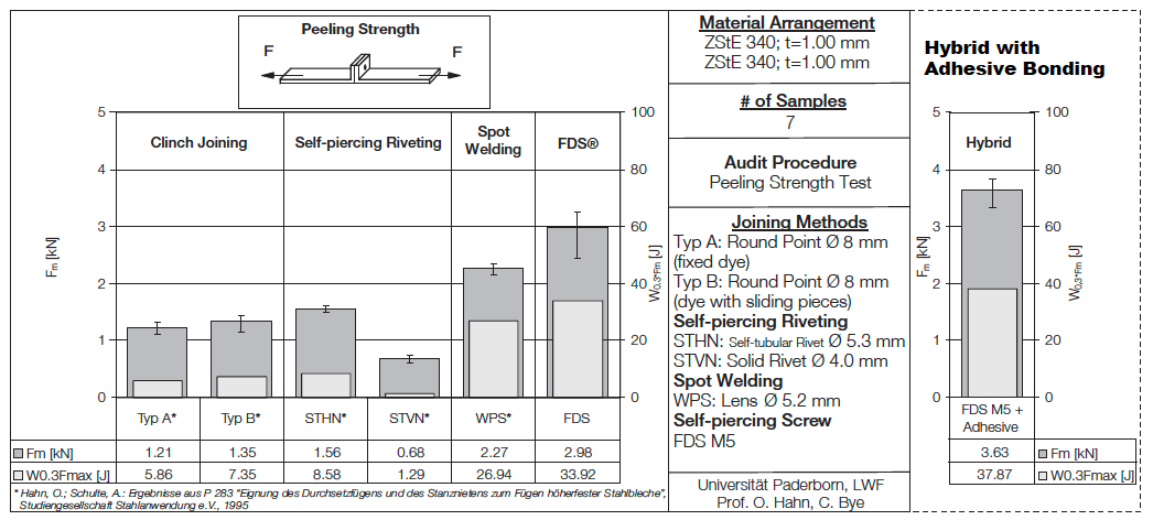
Peeling strength Fm and energy absorption F0.3*Fm of different joining methods in steel (ZStE 340)
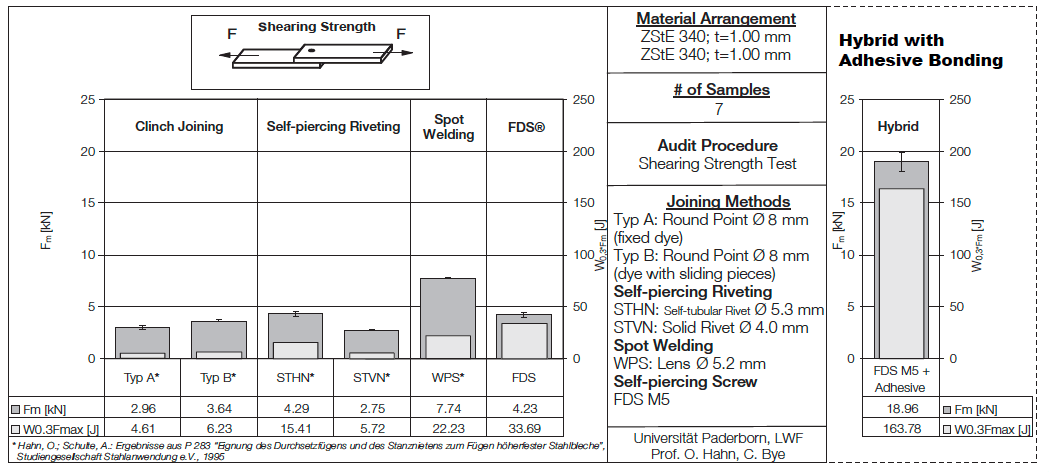
Shearing strength Fm and energy absorption F0.3*Fm of different joining methods in steel (ZStE 340)
NOTE: All data tables shown are for guidance purposes only.
Additional Family Products
![]()
Rapid Flow Drilling Screw Technology
Data Sheet(s)

 .
.